algemeen
> adressen
> test- en meetapparatuur
apparatuur foto's
> Philips PM2425 multimeter
> Sayrosa 261 frequentieteller
applicaties (pc)
> UI-View (APRS)
banden
> 27Mc
> FRS
> LPD
> PMR
componenten
> resistor coding
connectoren
> 12VDC connector
> Condor 16
> conenctoren [rf]
> TNC connector
documentatie
> boeken
> handleiding FUP1DZ
> jargon
> Morse code
> NATO alphabet
> Q-codes
> radio notebook
elektronenbuizen
> 6H2N-EB / ECC83 / 12AX7
> algemene informatie
> ATP4 elektronenbuis
> elektronenbuis codering
> elektronenbuizen
> gloeistroom/-spanning
> reactiveren/reformeren
> stabilisatiebuizen
filters/combiners
> Aerial Facilities BPD-410/420-3N
> Celwave P522 UHF duplexer
> JWX triplexer bc/2m/70cm
> Kenwood LF-30A LPF
> Motorola UHF cavity combiner
> Radiosystem RS490 cavity BPF
> stub filter [EN]
> basics: diplexer or duplexer
legerzenders
> AM-65/GRC
> LV-80 RF PA
> RT-70/GRC
> SEM antennetuner (AGAT)
> SEM25
> SEM25 gloeispanning
> SEM35
mechanica
> krimplak
> schroefdraad
> verspanen
meetapparatuur
> Daiwa CN-101L
> Daiwa CN-801
> x-tal tester (DIY project)
> Rigol DSA815-TG
> Spinner BN
> Spinner BN
> time standard; W5OJM
> Zetagi DL50 dummyload
meetapparatuur (info)
> (poor mans) spectrum analyser
> dummyload
> frequentieteller
> functiegenerator
> meetverzwakker
> octopus component tester
> staandegolfmeter
> timestandard
modificaties
> Yaesu MH-48 lock mod
naslagwerk
> (coax) kabels coderen
> APRS
> AWG draadtabel
> coax kabels testen
> paneelbouw
projecten
> (remote) coax switch
> afregelen FT-8x7(D)
> APRS basispost
> APRS tracker
> coax switch 1-8
> condensator microfoon
> dummyload (audio)
> FT-2000 headset
> FT-2000 remote
> FUP1DZS meetzender
> Geloso G.1/1040-A
> Geroh AKAC019 liermast
> go-kit
> headset (Avcomm)
> hoofdtelefoon versterker PL500
> Icom IC-25E
> Kerona AR-301 rotor
> KF-161 + Tinytrak 2
> KLV 400 RF PA ombouw
> Lineair 400W (Frinear)
> MFJ-948 antennetuner
> parallelle poort controller
> parallelle poort controller
> programmeren FT-8x7
> Samlex SEC 1223 voeding
> TH-D7E tracker
> Tinytrak 4
> uTracer 3+
> uTracer 3+
> voedingsconnector FT-897
> VSWR SA meetbrug
> Yaesu FT-857/897 meter
> zwaai Alinco DR-135E MkII
publicaties
> elektromigratie in filters
radioapparatuur
> Baofeng UV-5R
> Diamond X-30N rondstraler
> Icom IC-2e
> Kenwood TH-D7E
> Kenwood TS-830M
> MFJ-901b antennetuner
> MFJ-948 antennetuner
> Wouxun KG-UVD1P
> Wouxun speakermike
> Yaesu FT-101E
> Yaesu FT-2000
> Yaesu FT-7800
> Yaesu FT-857(D)
> Yaesu FT-897(D)
> Yaesu FT-8x7 serie
reparaties
> capacitors
> Geloso 3227 versterker
> Kenwood TS-830M
> Lorenz SEM25
> Lorenz SEM25
Rigol DSA815-TG
> meting: omroepband
> test: overspraak TG
> test: TG signaal
schakelingen
> elektret microphone
surplus apparatuur
> Bosch Condor 16
> Ericsson F-955
> Ericsson RS203/RS2062
theorie
> aarding
> antennetuner
werkplek
> workshop tips
veiligheid
> Beryllium oxide
> Beryllium oxide
> EM veldsterkte
> radioactiviteit
> harardous radioation?
|
|
introduction
|
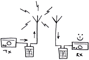
If there is a multi radio setup on the same site. The receiving station can be damaged by the strong electromagnetic fields of the transmitting antenna nearby. Therefore has the receiver to be protected against these string signals by filtering it. A stub filter can be the solution.

|
|
stub filter theory
|
A stub filter is the most simple filter you can imagine. It consists of, at least one, piece of coax cable of certain length. The length of the cable is related to the resonance frequency ant thereby also the frequency of the notch. The best way to explain the working is by an example;

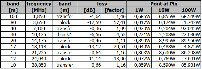
The speed of light/electrons is meter per second. The desired resonance frequency is 3,5MHz. According to the calculation results that in approximately 85,71 meters wavelength. The notch is at a quarter of the full wave, therefore the wavelength should be divided by four. That results in 21,43 meters. In theory, this should be the length of the stub. But since electrons travel slower trough coax than through free space, the speed (and length) has to be corrected. The "velocity factor" is normally known for each type of coax. In this example is RG-58 used with PE dielectric and has a velocity factor of 66% compared to free space. Therefore has the length of the stub (of 21,43 meters) to be reduced by 66% which results in a real length of 14,14 meters.
This piece of coax of 14,14 meters acts as a short circuit at 3,5MHz. If this frequency is multiplied by a odd number (3, 5, 7, and so on) the short circuit repeats at that frequency. Although each repeating notch is a little bit less "deep" due to losses in the cable. If this frequency is multiplied by an even number (2, 4, 6, and so on) the signal is damped for the minimum amount as possible.
A graphical view of this example is shown below.

The results can be also inverted. If the end of the stub is short circuited (the core connected to the shielding), the results are inverted.
|
|
stub filter in practice
|
As you can see in the example above, the ham bands are recognizable. 80, 40, 30, 20, 17, 15, 12 and 10 meter bands are visible. When two filters are made as described, one with an open end and one with a closed end, those can be very helpful. If two radio setups are very close, the receiving radio can be damaged by the large incoming signals of the nearby station. Even if the receiving station is at another frequency than the transmitting station. If station A is using the 3,5MHz open stub, it can be used on 7, 14, 21 and 28MHz since the signal is let trough. Spurious radiation on the 3,5, 10,5, 17,5 and 24,5MHz are suppressed in the stub filter. If station B is using the 3,5MHz closed stub, it can be used on 3,5, 10,5, 17,5 and 24,5MHz since the signal is let trough. Spurious radiation on the 7, 14, 21 and 28MHz are suppressed in the stub filter. The result is that both stations can operate simultaniously without interference of each other.
It is possible to use more stubs (of different lengths) in one filter. Keep in mind that the unwanted losses can be much more.
|
|
adjustment
|
|
The adjustment is quite simple. Using a spectrum analyser with tracking generator shows the notches. By cutting the (too long) coax will shift the notches to a higher frequency. Keep cutting the coax untill the notches are at the desired frequency of frequencies. After cutting the coax to the desired length, the open end can be "closed" by connecting the core to the shielding.
|
|
my experiences; first design
|
|
The initial plan was to make filters for using 10, 20 and the 40 meter bands with two radio's. I started to make three filters with two stubs to suppress the other two unused bands. Since two stubs are used in one filter, the losses for the usable band were quite large. Therefore a design change is made
|
|
my experiences; second design
|
Instead of two stubs, one stub for 3,5MHz is used. One closed stub and one open stub. The losses were less than two stub design. If there are more than two radio's on the same site, multiple stubs are necessary for the right combination. Since I planned to used "only" two radio's the 3,5MHz stub will do the job. 50% of the bands are for radio A and the other ham bands are for radio B. The 30 meter band is not optimally suppressed since the notch is slightly next to the band. Since we do not use telegraphy, this is accepted.

It is possible to use a piece of coax and a coax tee, but I chose to use new paint cans as a housing. Two connectors are mounted at the lid of the can and a wire bridge is created between the connectors. The piece of coax is connected to the wire bride and the wire is cut to length using a spectrum analyser with tracking generator. The wire end is isolated and the wire is put into the can. The final measurement is made with the lid onto the can. The result of can one is shown below.

|
|
credits
|
The creation/adjustment of this kind of filter is inspired by a YouTube video of Alan; W2AEW. The video is shown below.
|
|
